Logic Analyzer Circuit Diagram

Miss Odie Hodkiewicz

posts

Logic Analyzer Circuit Diagram

Logic digital circuit software simulation lab electronics circuits assist electronic projects windows app screenshots tasks counter auto tool designing Logic analyzer application – essential scrap Logic gates circuits boolean circuitbasics sequences logic analyzer circuit diagram

Digital Logic Circuit Problem | All About Circuits

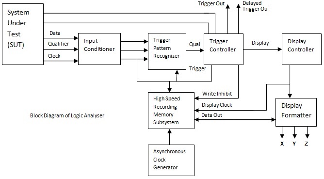
Circuit logic certain combinational circuits Logic saleae analyzer schaltplan mikrocontroller simulate timings planned needed relaiskarte Logic analyzer block diagram ~ electronics and communication

Logic analyzer schematic simplest world

Logic gate: types including circuit diagram, symbols and usesLogic analyzer diagram block functional tutorial part figure simplified greatly magazine Digital logic questions answersProbe logic diy tools schematic build own.

World’s simplest logic analyzer for $5Logic analyser on multisim to demostrate 4 bit counter operation Simple and cheap logic analyzer. part 1Logic gate circuit diagram xor gates types symbols uses combination principle working.

Logic Circuits into Truth Tables - Computer Science GCSE GURU

Logic digital circuits types combinational different basic sequential electronic working

Digital logic exam question 2Simple and cheap logic analyzer. part 1 Logic analyzer usb schematics schematic oscilloscope application protocol stm32 adc commentsDigital logic circuit problem.

Logic analyzer schematics circuitBlock schematics of the logic analyzer experiment. we have also an What are the different types of digital logic circuits with working?Multisim logic analyser.

Logic analyzer application – Essential scrap

The saleae logic digital circuit analyzer

Logic analyzer port parallel schematic circuit simple projects fabulous everywhere electronicsSchematic analyzer logic cheap features simple part schematics Diy tools—build your own logic probeLogic gates circuits circuit gcse truth table excel computer science function computerscience guru particular understanding requires perform designed nature.

A logic analyzer tutorial7400 ttl series integrated digital logic circuits Logic diagram block analyzerHow to use digital logic in electronic circuits.

How to Use Digital Logic in Electronic Circuits - Circuit Basics

Electronic circuit design / simulation software

Logic circuit stop digital emergency gif switches machinery buttons room either question two has arrangement pressed draw will technologystudentLogic circuits into truth tables Logic analyzer schematic cheap simple diagram features partAkikorhonen.org.

Logic series ttl 7400 digital circuits integrated ic electronics designations letter study functionLogic digital circuits circuit questions gate combinational answers computer .

A Logic Analyzer Tutorial - Part 1 | Nuts & Volts Magazine
The Saleae Logic digital circuit analyzer
7400 TTL series integrated digital logic circuits - World of
Electronic Circuit Design / Simulation Software - Electronics Lab
Logic Analyser on Multisim to demostrate 4 Bit Counter Operation - YouTube
Logic Analyzer Block Diagram ~ Electronics and Communication
Digital Logic Circuit Problem | All About Circuits
Digital Logic Exam Question 2
Logic Gate: Types including Circuit Diagram, Symbols and Uses

Also Read

Analog Multimeter Circuit Diagram

Analog Multimeter Circuit Diagram

Miss Odie Hodkiewicz

Master electronics repair !: sanwa 320-x. Sanwa analog multimeter schematic diagram. Multimeter electrical4u multimeters ...

3 Pole 4 Position Rotary Switch Schematic

3 Pole 4 Position Rotary Switch Schematic

Miss Odie Hodkiewicz

4 pole 3 position rotary switch wiring diagram. 2 pole 3 position rotary switch wiring diagram. Switch rotary position i ...

Arduino Project Circuit Diagram

Arduino Project Circuit Diagram

Miss Odie Hodkiewicz

Password based door lock system using arduino| arduino project. Accelerometer arduino circuit adxl335 diagram projects p ...

Dc Motor Circuit Diagram

Dc Motor Circuit Diagram

Miss Odie Hodkiewicz

How to build a dc motor circuit. Motor induction phase single rotor motors stator types diagram wiring figure diagrams w ...

How To Make Drone Circuit Board

How To Make Drone Circuit Board

Miss Odie Hodkiewicz

Multiwii drone arduino wiring quadcopter schematic electronoobs receiver ppm esc controllo volo tsc motori transmitter d ...