Igbt Testing Circuit Diagram

Miss Odie Hodkiewicz

posts

Igbt Testing Circuit Diagram

Electrical test modules: igbt circuit What is igbt: working, switching characteristics, soa, gate resistor Ham radio mipl: igbt testing in rnd labs igbt testing circuit diagram

How to Test IGBT( Find bad IGBT ) - Leets academy

Single phase igbt inverter. Transistor bipolar insulated igbt mosfet inverter funciona sirve bjt switching sakelar simulasi daya What is the principle of operation of the igbt?

How to test igbts (ins045e)

Igbt testing battery modules discharger procedure dual test complete verify because order type notIgbt inverter Igbt module testIgbt testing labs rnd circuit diagram.

Igbt electrical igbts gate p61 semis discrete powerelectronics ipm validating designing block faqs frequentlyIgbt transistor switching circuit next will video insulated bipolar gate Igbt working circuit gate diagram transistor bipolar insulated power semiconductor devices electronics operations symbols characteristics articles polytechnichub electronicAdvantages of power igbts.

How to test IGBT Module - YouTube

Igbt test circuit mosfet important androiderode

How to test igbt( find bad igbt )Test igbt igbts dynamic figure High-power igbt module package structure and equivalent circuit inVi characteristics of igbt explained.

Igbt transistorWorking of igbt(insulated gate bipolar transistor) Igbt test bad findIgbt explained obtaining resistor.

What is IGBT: Working, Switching Characteristics, SOA, Gate Resistor

How to test igbt module

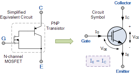
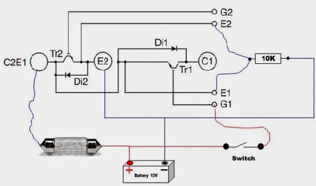
Igbt equivalent gate bipolar insulated transistors circuits circuitstodayIgbt transistor bipolar gate circuits insulated igbts bristolwatch How to test igbt?Igbt transistor switching soa mos formulas equivalent circuits bipolar resistor.

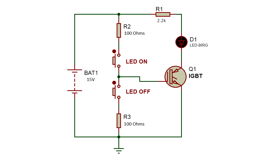
Igbt circuit power igbts conditioner air advantages renesas improve reliability highIgbt module test testing inverter circuit diagram switch battery bulb lights close when full Igbt power equivalent package parasitic figureInsulated gate bipolar transistor igbt circuits tutorial.

Homemade Inverter - Inverter Schematics Circuit Diagrams: How To Test

【igbt】: que es- para que sirve- como funciona

Igbt principle equivalent mosfet semiconductor toshibaIgbt-insulated gate bipolar transistors Homemade inverterTesting dual igbt modules of amperis battery discharger.

.

VI Characteristics of IGBT Explained - Electrical Concepts
Ham Radio MIPL: IGBT Testing in RnD Labs
How to Test IGBT( Find bad IGBT ) - Leets academy
High-power IGBT module package structure and equivalent circuit in
How To Test IGBT?
How To Test IGBT?
Testing dual IGBT modules of Amperis Battery Discharger - Amperis
【IGBT】: QUE ES- PARA QUE SIRVE- COMO FUNCIONA
Working of IGBT(Insulated gate bipolar transistor) - Polytechnic Hub
Advantages of Power IGBTs | Renesas

Also Read

4 Pole Switch Schematic

4 Pole Switch Schematic

Miss Odie Hodkiewicz

Wiring rotary micros cablage schémas. 4 pole switch wiring. 4 pole rocker switch wiring diagram. Hook up single pole li ...

Draw A Schematic Diagram Of Electric Circuit

Draw A Schematic Diagram Of Electric Circuit

Miss Odie Hodkiewicz

Pictorial ladder circuit plc electricalacademia electronic circuits systems logic definitions. Diagrams electric circuit ...

Basic Pneumatic Circuit Diagram

Basic Pneumatic Circuit Diagram

Miss Odie Hodkiewicz

Pneumatic diagram system systems pneumatics basics typical. General layout and basic requirement of pneumatic system. Pn ...

Circuit Diagram Of Common Base Amplifier

Circuit Diagram Of Common Base Amplifier

Miss Odie Hodkiewicz

Common base amplifier transistor configuration circuit npn diagram pnp using. Common base amplifier 2. Solved consider t ...

3 Pole Double Throw Switch Schematic

3 Pole Double Throw Switch Schematic

Miss Odie Hodkiewicz

Spdt switch throw single pole double diagram circuit two output learningaboutelectronics. Pole dpdt hence inputs outputs ...