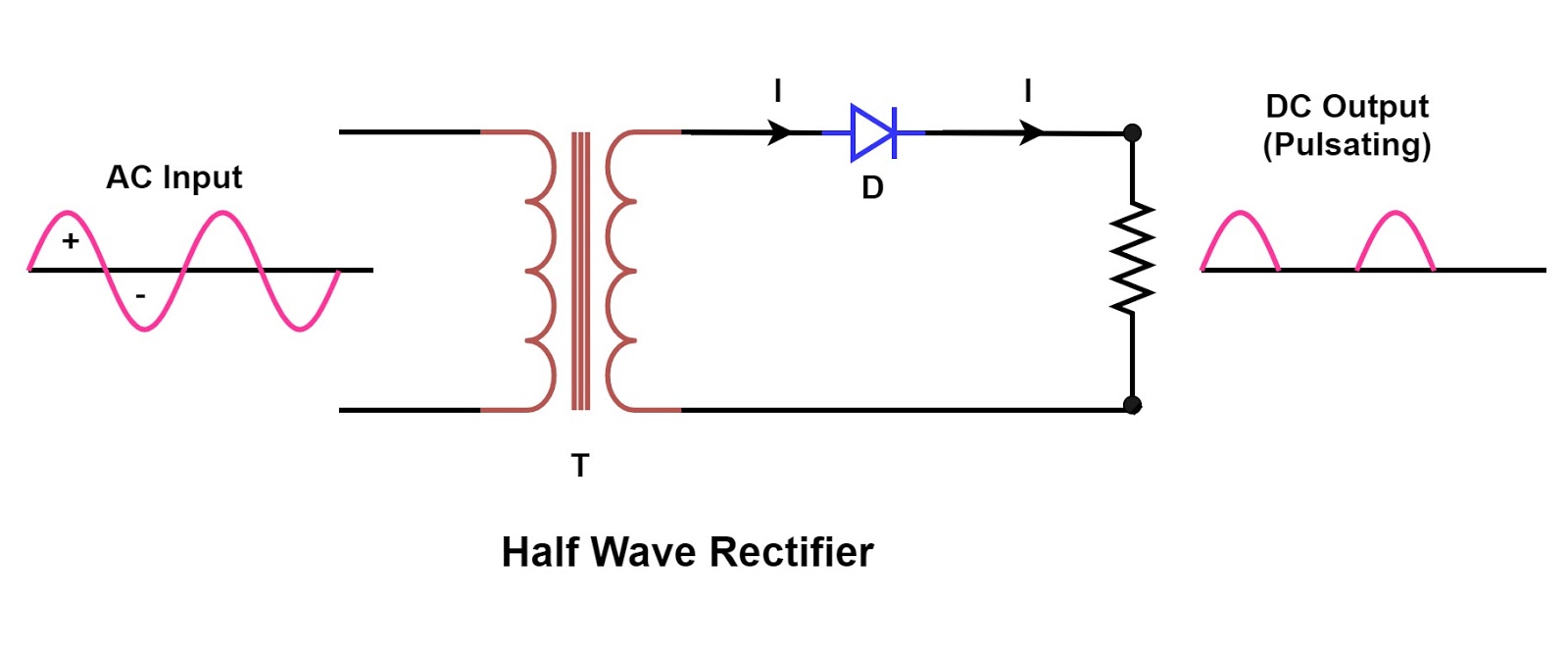
Half Wave Rectifier Circuit Diagram

Miss Odie Hodkiewicz

posts

Half Wave Rectifier Circuit Diagram

☑ filter capacitor formula for half wave rectifier Rectifier wave half full circuit diode voltage diagram output waveform ac figure input positive cycle dc principle working converts Half wave & full wave rectifier half wave rectifier circuit diagram

Half Wave Rectifier - Definition, Working, Formula, Applications

Rectifier circuit half wave diagram fast build forget don if click Rectifier halfwave difference byjus formula Build a fast half-wave rectifier circuit diagram

Rectifier circuit input waveform

What are half-wave rectifiers? definition, circuit and working of halfRectifier circuit diagram Rectifier circuit principle acSingle phase half wave rectifier- circuit diagram,theory & applications.

Half wave rectifierWave rectifier half circuit diagram hwr Rectifier capacitor diode circuits load rl circuitstoday 2009Half wave rectifier.

What are Half-Wave Rectifiers? Definition, Circuit and Working of Half

Wave half rectifier diode ac voltage supply output circuit peak inverse dc piv operation value load average input when resistance

Half wave rectifier – definition, working, circuit diagram, theoryHalf and full wave rectifier working principle Wave half circuit rectifier diagram rectifiers working represents below figure.

.

Half Wave Rectifier – Definition, Working, Circuit Diagram, Theory
Single Phase Half Wave Rectifier- Circuit Diagram,Theory & Applications
half wave rectifier | ECE Tutorials
☑ Filter Capacitor Formula For Half Wave Rectifier
Build a Fast half-wave Rectifier Circuit Diagram | Electronic Circuit
Half and Full Wave Rectifier Working Principle | Circuit Diagram
Rectifier Circuit Diagram | Half Wave, Full Wave, Bridge - ETechnoG
Half Wave & Full Wave Rectifier | Working Principle | Circuit Diagram
Half Wave Rectifier - Definition, Working, Formula, Applications

Also Read

Op Amp Tester Circuit Diagram

Op Amp Tester Circuit Diagram

Miss Odie Hodkiewicz

Op amp tester circuit test ic. Tester transistor circuit opamp single seekic. Op amp clipping motor using operational ci ...

Seal-in Circuit Diagram

Seal-in Circuit Diagram

Miss Odie Hodkiewicz

What is seal-in circuit ?. Circuit seal start latching button momentary pressed switch fig not instrumentationtools work ...

Custom Chopper Wiring Diagram

Custom Chopper Wiring Diagram

Miss Odie Hodkiewicz

Wiring diagram chopper mini 49cc chinese razor gas scooter 43cc engine harley carburetor yamaha. Live to ride ride to ch ...

What Is A Voltage Stabilizer

What Is A Voltage Stabilizer

Miss Odie Hodkiewicz

Protect your home appliances with a voltage stabilizer. 4000va automatic voltage stabilizer. Stabilizer principle autotr ...

How To Rotate Schematics In Litematica

How To Rotate Schematics In Litematica

Miss Odie Hodkiewicz

Litematica schematics using. Loaded schematics turn into a mess · issue #61 · maruohon/litematica ...