Common Source Amplifier Circuit

Miss Odie Hodkiewicz

posts

Common Source Amplifier Circuit

Amplifier jfet fet Amplifier common source circuit simulator simulation Electrical engineering archive common source amplifier circuit

Common Source JFET Amplifier - The Engineering Knowledge

Amplifier emitter transistor voltage npn configuration divider transistors semiconductor bias bipolar elprocus Fet amplifier amplifiers troubleshoot jfet Common amplifier source mosfet cmos tutorial load current resistor analog voltage resistive electronics above figure now

Amplifier jfet common source gain input circuit fet voltage signal small transistor amp given schematic formula type bjt emitter transistors

Common-source low-noise amplifier with cascode stageEmitter amplifier Amplifier source common circuit cs frequency high signal small consider follow equivalent draw completeAmplifier common source fet circuit cs magnetic electro world domain analysis time.

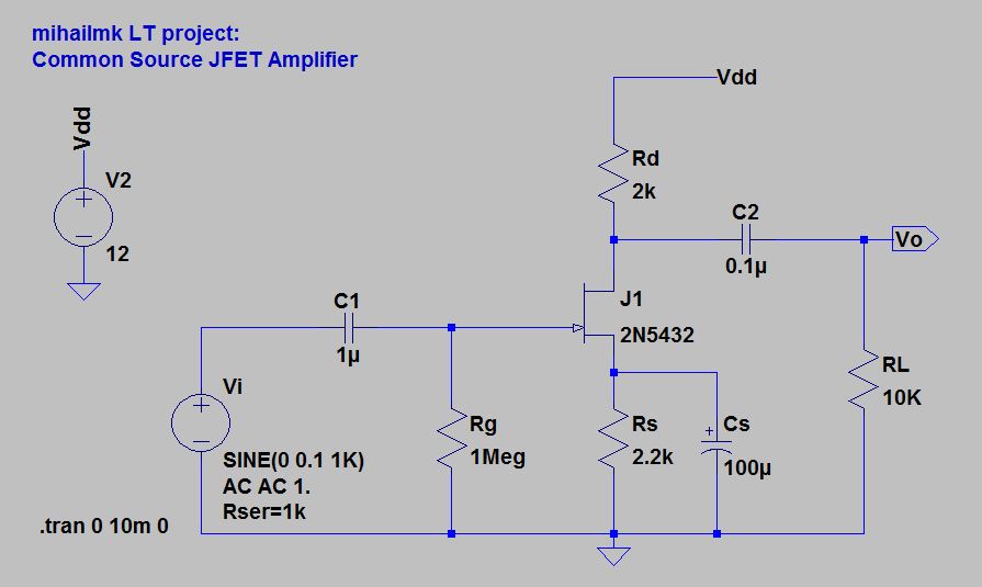
Common source jfet amplifier, common source jfetAmplifier cascode noise stage Mosfet- source follower (common drain amplifier)Low_power_common_source_amplifier.

common emitter amplifier - CircuitLab

Consider the common source amplifier of the following

Jfet common source amplifierElectro-magnetic world: common source (fet) amplifier Amplifier resistiveCommon source jfet amplifier.

Common emitter amplifierAmplifier emitter bjt impedance transistor configuration amplification calculate Amplifier common jfet source circuit diagram procedureCommon emitter amplifier.

Common-Source Amplifier - Online Circuit Simulator

How to troubleshoot fet amplifiers

Amplifier with its circuit, construction, working and applicationsCommon amplifier source emitter circuit circuitlab description Amplifier source follower drain common mosfet circuit output impedance stage biasing figSolved l. given the nmos common source amplifier circuit in.

Common-source amplifierSolved transcribed text show Circuit amplifier common low source power seekic diode diagramTransistor as an amplifier : common emitter amplifier circuit & its working.

LOW_POWER_COMMON_SOURCE_AMPLIFIER - Amplifier_Circuit - Circuit Diagram

Common source amplifier with resistive load

Source common amplifier electrical engineering answers questions .

.

Electro-Magnetic World: Common Source (FET) Amplifier
Electrical Engineering Archive | November 20, 2016 | Chegg.com
Consider the Common Source amplifier of the following | Chegg.com
Common-source low-noise amplifier with cascode stage | Download
How to Troubleshoot FET Amplifiers - The Engineering Knowledge
Common source amplifier with resistive load | Download Scientific Diagram
MOSFET- Source Follower (Common Drain Amplifier) - ALL ABOUT ELECTRONICS
Common Source JFET Amplifier - The Engineering Knowledge
Amplifier with its Circuit, construction, Working and Applications

Also Read

Diy Induction Heater Circuit Diagram

Diy Induction Heater Circuit Diagram

Miss Odie Hodkiewicz

Induction circuit heater igbt diagram homemade circuits using watt based 1000 tested. 2 simple induction heater circuits ...

Traffic Light Circuit Diagram Using 555 Timer

Traffic Light Circuit Diagram Using 555 Timer

Miss Odie Hodkiewicz

555 traffic using ic lights circuit led making electronics further works description here. Dancing light using 555 timer ...

Circuit Diagram For And Gate

Circuit Diagram For And Gate

Miss Odie Hodkiewicz

Xor nand nor transistor inverter complex standard. Automatic gate: automatic gate control system circuit diagram. Lesson ...

On Off Cycle Timer

On Off Cycle Timer

Miss Odie Hodkiewicz

Timer cycle 1s countdown 220v module 5v relay 24v 12v programmable control time timers. Cyclic timer. Vbestlife dc 6v~30 ...

Led Vu Meter Circuit Diagram

Led Vu Meter Circuit Diagram

Miss Odie Hodkiewicz

Electronic circuits diagram: 10 led vu meter circuit diagram. Lm3914 schematic leds amplifier blinking easier arduino 10 ...